
60 seconds in a minute. 60 minutes in an hour. Simple and straightforward, right? Perhaps, but predictability plays a role too. ‘One moment we had waiting hours, the next we had to work at the weekend.’
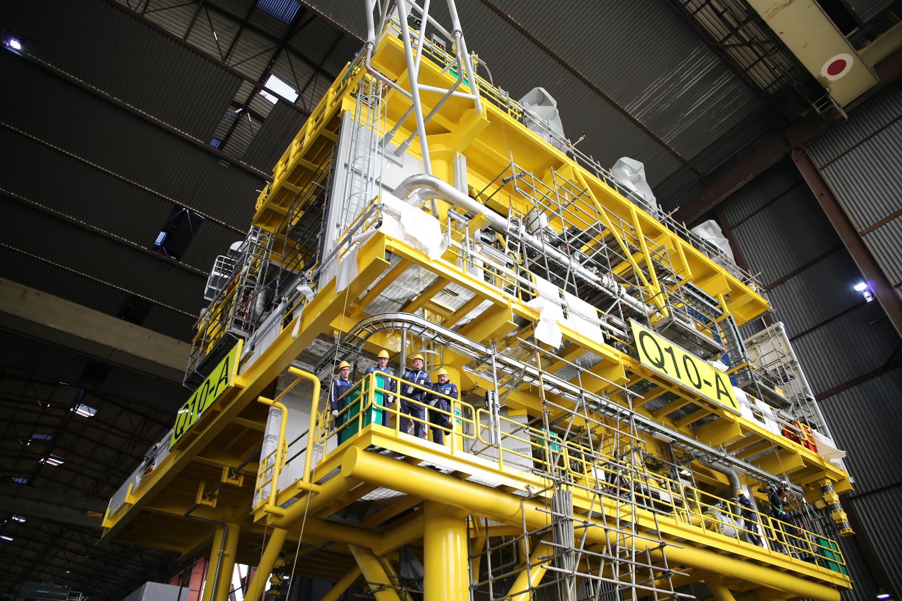
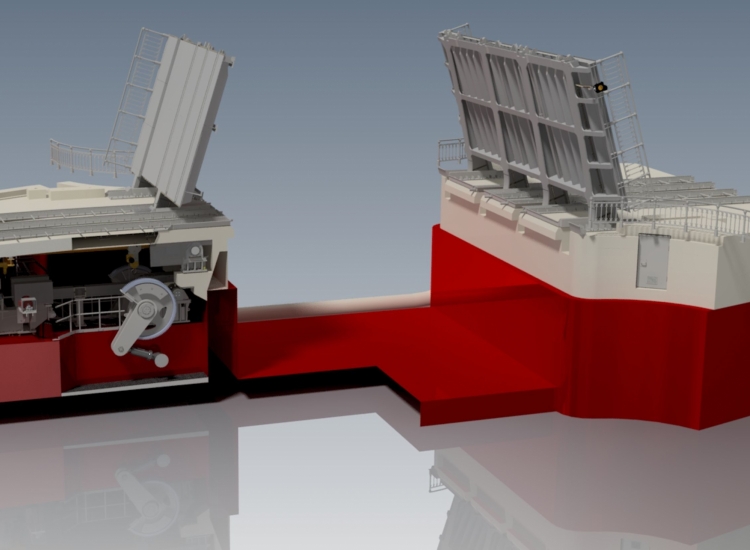
Offshore is one of the markets in which VIRO is active. Last year, a builder of offshore platforms, jackets, and modules was looking to expand its external engineering capacity. ‘Topsides (the part of offshore platforms above sea level) can weigh anywhere from a few hundred tonnes up to twelve thousand tonnes, and sometimes even more. Designing topsides therefore requires a large team of Tekla modellers/engineers,’ explained Yoran Volkers, Hillebrand Lucas, Jos Broekroelofs, and Christiaan Derksen of VIRO. They were involved in the topside engineering for the Q10 gas field in the North Sea, off the coast of Ijmuiden.
As-built drawing packages
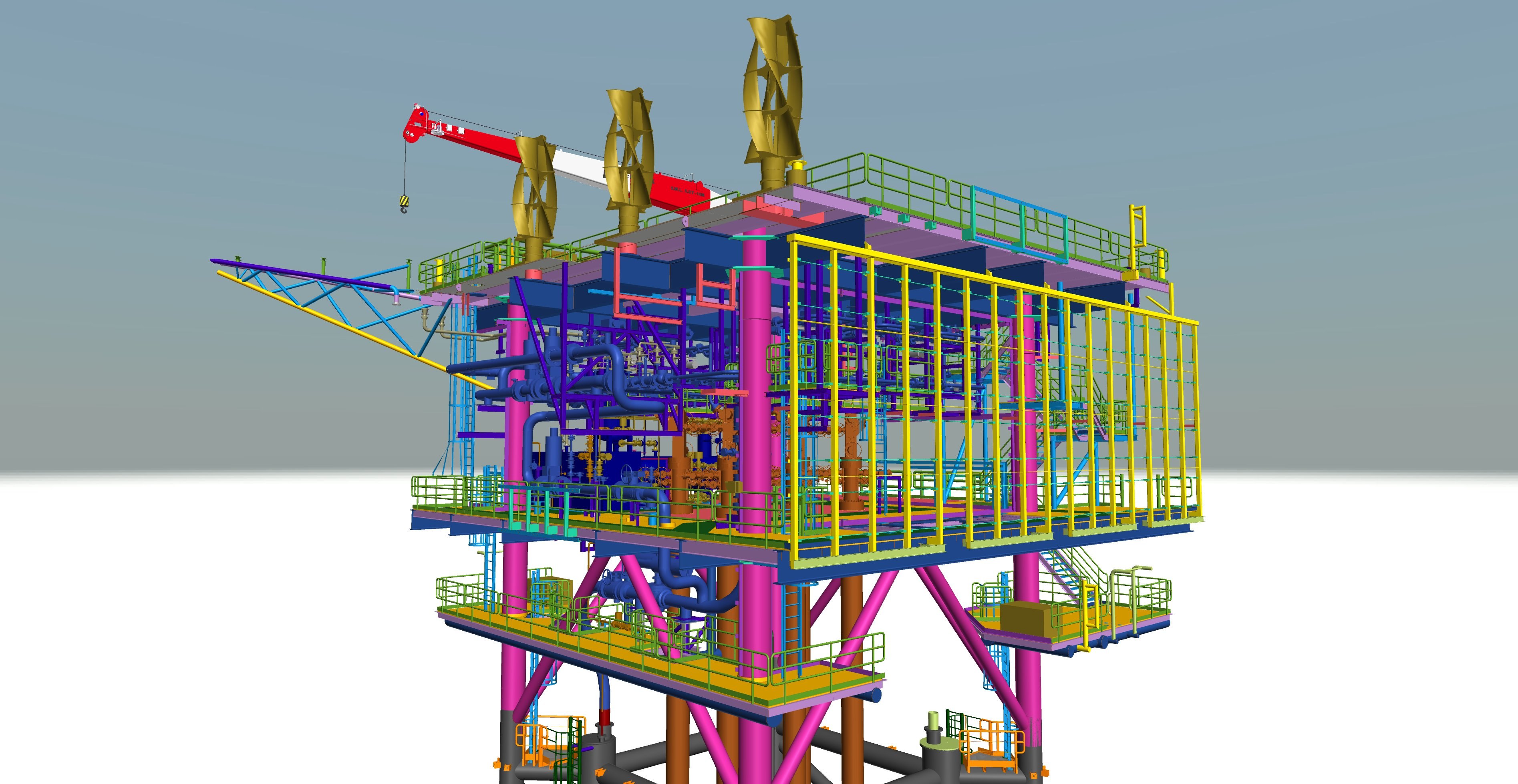
‘We were asked to model the topsides entirely in 3D. Then we also made the production packages in Tekla Structures. The whole project had to be drawn as-built. Normally, for example, welding and pre-welding activities are merely noted with an indication and accompanied by an information label on workshop drawings. For this project, each and every one was drawn in the 3D model. A 25 mm full penetration weld was modelled exactly as such, including a base material cutaway.
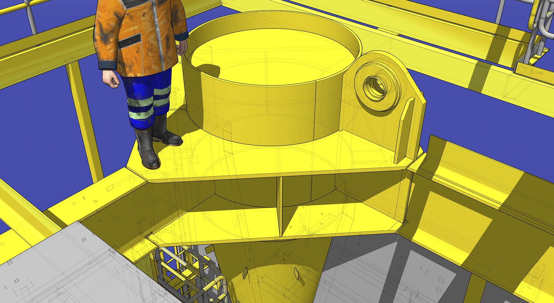
In total, Q10 involves nearly 10,000 welds with a total length of 4.5 kilometres, that had to be accurately drawn. This approach was chosen because the customer’s production machinery can also read the location, length, and weight of the welds. This is one of the factors allowing them to determine the production turnaround time.’ In order to be able to provide the workshop with guaranteed consistency of the drawing quality, we produced the drawings in accordance with our customer’s standards: ‘We studied this in depth. Particularly during the early stages, we spent many weeks at the client’s site, purely to gather information. The people on location provided this information to the engineers in Hengelo and Arnhem.’
Time is money
Time pressure was inevitable in this case. The business case for this type of project stands or falls with the oil prices. Fluctuating prices pose a risk to the backers. If the price falls below a critical level, a project can be put on hold. As soon as the go-ahead is given for an oil and gas platform, it must be up and running quickly. Often the original roll-out date (the date that the platform has to roll out of the production facility) remains unchanged during the on-hold period. In other words, when this happens there is less time left for engineering and production between the go-ahead and roll-out. Often the builder has to pay heavy fines for late delivery. Reason enough, then, to develop the drawing packages with a fast-track method.
Fast-track method
‘We decided to start working on it based on the AFD drawings (the preliminary drawings) we received from the design house. They already contain enough information to start the drawing work. Sometimes, in a totally unexpected moment, we would receive a major change. One Friday afternoon when we were about to deliver a large production package, a major change to that package came in just minutes beforehand. That kind of thing can happen, and it’s something you just have to accept. The other option is to wait two months for the final drawings. Suppose an extra month’s work is required for the fast-track method; you will have still saved a month in terms of when you’re finished. In consultation, the customer had therefore clearly chosen this method.’
Overload
The design house also worked under extreme pressure. In order to encourage the timely supply of input (design drawings), our engineers occasionally took over work from the design agency. ‘Because it wasn’t clear exactly when we would receive updated drawings, it was very difficult to plan the personnel deployment. We went from one extreme to the other: from waiting hours to lack of capacity. During the engineering peak, we were working simultaneously on AFD drawings, AFC drawings, deliveries, changes from design, and changes from production. The drawings went to production as soon as they were finished. Because new work packages were ready almost daily during the busy period, the flow of information was too high for just a single QA controller. ‘We even had to scale up with someone from our mechanical engineering department in Hengelo.’ A total of 11 people from Hengelo and Arnhem were actively involved in this project.
Up-to-date WBS
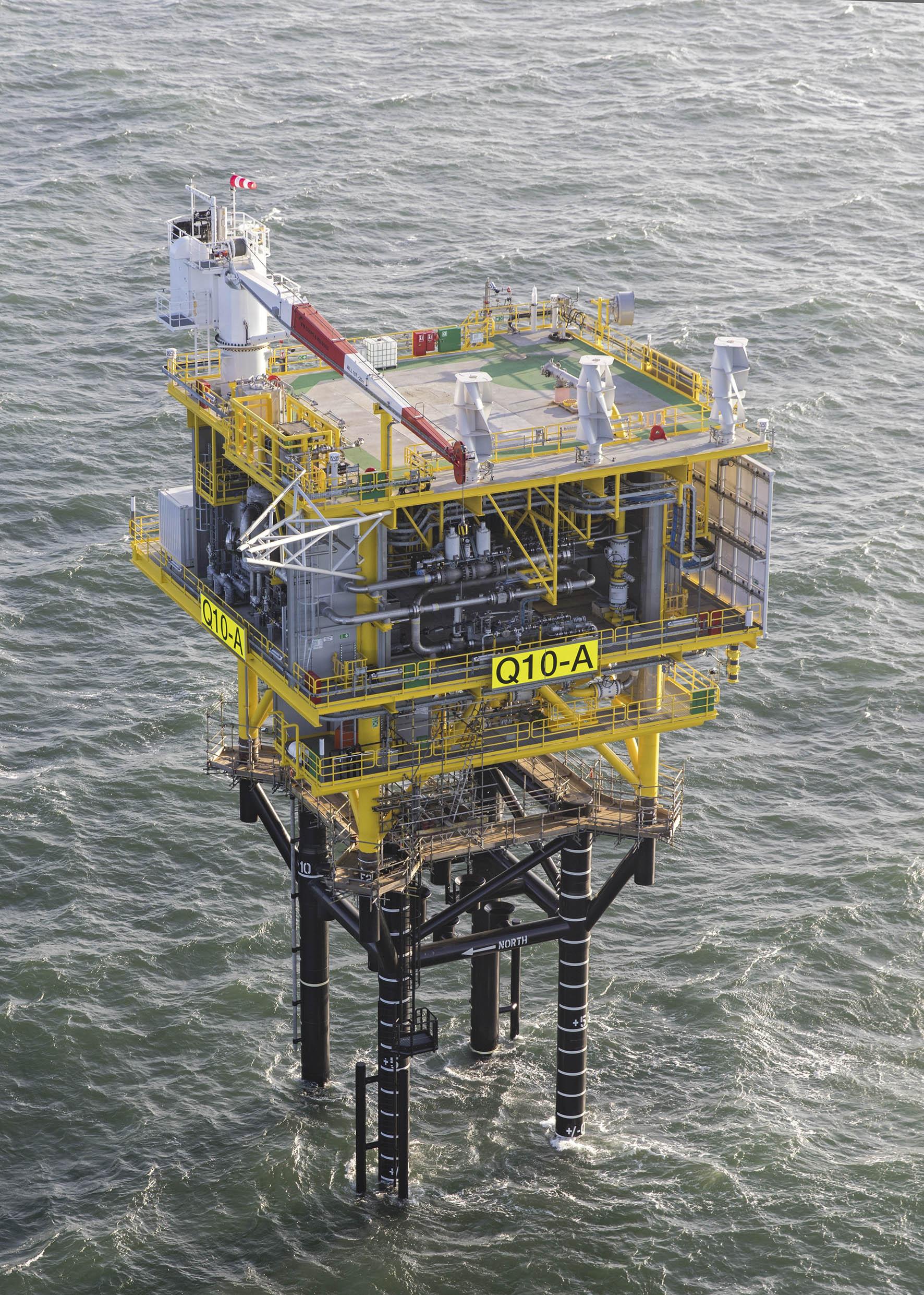
Close management was key. An extensive work breakdown structure (WBS) was the common thread running through the project management. In the WBS, the project was divided into increasingly smaller projects down to the level of the work packages. ‘With such an enormous flow of information, you need a visual means of communication: what is the current status, how much have we already done, what is still to come?’ In all these information flows, you also need to keep track of the big picture and maintain a helicopter view: ‘For example, one modeller was responsible for all changes. He made sure the shared cloud model was always up to date, to ensure the other modellers were working in the most recent model.’ And the result? ‘Over the course of a concerted team effort over five-months, we delivered almost 6,000 drawings in 150 production packages. Eventually, due to some external factors, the roll-out of the platform was two weeks later than planned; the platform is now standing firmly on the bed of the North Sea. The client was very satisfied with VIRO’s work. Its quality exceeded expectations.’